I/O Interface Specifications
| Parameter | Value | Unit | Remarks |
| Input Voltage | 8 – 36 | V | |
| Output Voltage (12V) | 12 | V | Max. 4 A (Includes pyro channels) |
| Output Voltage (5V) | 5V | V | Max. 2 A |
| Pyro Channels | 4 | ch | Powered from 12 V rail |
| PWM Output Channels | Up to 8 | ch | Shared with UART pins |
| UART Interfaces | Up to 3 | ports | Shared with PWM pins |
| Accelerometer | ±32 | G | |
| Gyroscope | ±4000 | dps | |
| Pressure | 300 – 1200 | bar | |
| Magnetometer | ±800 | uT |
System Operation
Firmware Update
If “Application” is displayed, press the mode switch button and transition into the bootloader.
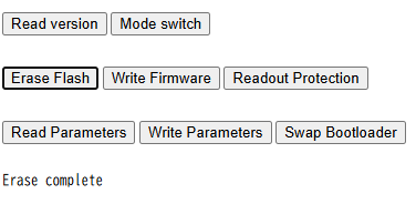
Next, press the erase flash button to erase the firmware.When it finishes, “Complete” will be displayed.
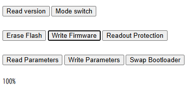
Press the “Write Firmware” button to update the firmware. Once it shows 100%, it is complete.By pressing the mode switch and starting the firmware, you will have successfully updated the firmware.
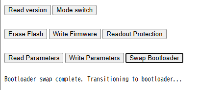
Bootloader Update
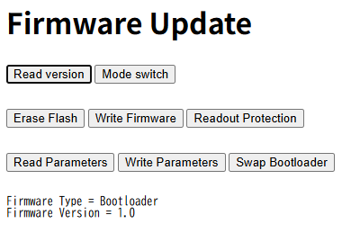
Press the “Read Version” button and confirm that “Application” is displayed as running.If “Bootloader” is displayed, press the mode switch to move to the application.
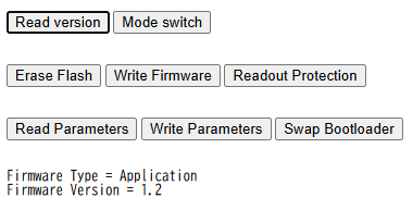
When the bootloader update completes, “Complete” will be displayed.Upon completing the bootloader update, the system switches into the bootloader mode. During the bootloader update, make sure the power is never turned off.